Standard Dimensions
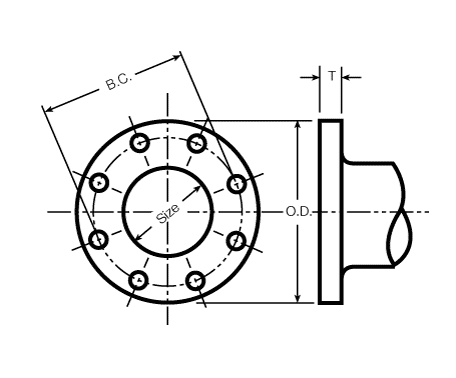
Flange Details
ANSI/AWWA C110/A21.10, C111/A21.11 or C153/A21.53
The flanges shown are adequate for water service of 250 psi working pressure and should not be confused with class 250 flanges per ANSI B16.1. The bolt circle and the bolt holes match those of ANSI B16.1 class 125. If flanges are required to be made in accordance with other ratings or other standards, this must be specified on the purchase order. 24" and smaller flanges are rated equal to the fittings to which they are attached and are adequate for water service of greater than 350 psi only with the use of AMERICAN’s Toruseal gaskets.
We recommend that AMERICAN Toruseal gaskets be used for normal water service.
Facing: Flanges are plain faced and are finished smooth or with shallow serrations (AMERICAN’s option).
Back Facing: Flanges may be back faced or spot faced (AMERICAN’s option), for compliance with the flange thickness tolerance.
Drilling: Drilling of flanges can be rotated when required; for those sizes with an even number of bolt holes in each quadrant, the fitting can be rotated 45° with standard drilling.

| Size (in.) |
O.D. (in.) |
B.C. (in.) |
T (in.) |
Bolt Hole Diameter (in.) |
Bolts | |
|---|---|---|---|---|---|---|
| No. Per Joint |
Size (in.) |
|||||
| 3 | 7.50 | 6.00 | 0.75 | 3/4 | 4 | 5/8 × 2 1/2 |
| 4 | 9.00 | 7.50 | 0.94 | 3/4 | 8 | 5/8 × 3 |
| 6 | 11.00 | 9.50 | 1.00 | 7/8 | 8 | 3/4 × 3 1/2 |
| 8 | 13.50 | 11.75 | 1.12 | 7/8 | 8 | 3/4 × 3 1/2 |
| 10 | 16.00 | 14.25 | 1.19 | 1 | 12 | 7/8 × 4 |
| 12 | 19.00 | 17.00 | 1.25 | 1 | 12 | 7/8 × 4 |
| 14 | 21.00 | 18.75 | 1.38 | 1 1/8 | 12 | 1 × 4 1/2 |
| 16 | 23.50 | 21.25 | 1.44 | 1 1/8 | 16 | 1 × 4 1/2 |
| 18 | 25.00 | 22.75 | 1.56 | 1 1/4 | 16 | 1 1/8 × 5 |
| 20 | 27.50 | 25.00 | 1.69 | 1 1/4 | 20 | 1 1/8 × 5 |
| 24 | 32.00 | 29.50 | 1.88 | 1 3/8 | 20 | 1 1/4 × 5 1/2 |
| 30 | 38.75 | 36.00 | 2.12 | 1 3/8 | 28 | 1 1/4 × 6 1/2 |
| 36 | 46.00 | 42.75 | 2.38 | 1 5/8 | 32 | 1 1/2 × 7 |
| 42 | 53.00 | 49.50 | 2.62 | 1 5/8 | 36 | 1 1/2 × 7 1/2 |
| 48 | 59.50 | 56.00 | 2.75 | 1 5/8 | 44 | 1 1/2 × 8 |
| 54 | 66.25 | 62.75 | 3.00 | 2 | 44 | 1 3/4 × 8 1/2 |
| 60 | 73.00 | 69.25 | 3.12 | 2 | 52 | 1 3/4 × 9 |
| 641 | 80.00 | 76.00 | 3.38 | 2 | 52 | 1 3/4 × 9 |
Flanged Fitting Dimensions and Designation of Outlets
ANSI/AWWA C110/A21.10, C153/A21.53, or AMERICAN Standard

See the table below for dimensions for the above fittings. Some of the above fittings are not listed in AWWA C110, but do meet applicable requirements of AWWA C110.
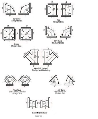
The largest opening establishes the basic size of a reducing fitting. The largest opening is named first, except for bull-head tees and for double-branch bends where both branches are reducing; in these two cases the largest opening is named last.
In the designation of the openings of reducing fittings, they should be read in the order indicated by the sequence of the numbers 1, 2, 3 and 4 as shown.
In describing tees reducing on the branch only, the first size applies to both outlets on the run. Similarly, for crosses with the same size for both run outlets and the same size for both branch outlets, it is necessary to indicate only two sizes. For example: for an 8 × 6 tee or wye – it is not necessary to show 8 × 8 × 6; for an 8 × 6 cross – it is not necessary to show 8 × 8 × 6 x 6.
| Size (in.) |
Dimensions2 in Inches | Reducing Tees and Crosses |
Reducing Wyes3 | ||||||||||||||
|---|---|---|---|---|---|---|---|---|---|---|---|---|---|---|---|---|---|
| A | B | C | D2 | E2 | F | R | S (Dia.) |
T | U | Size of Branches and Smaller5 | H | J | Size of Branches and Smaller | M | N | P | |
| 3 | 5.5 | 7.75 | 3.0 | 10.0 | 3.0 | 6 | 4.88 | 5.00 | 0.56 | 0.50 | - | see6 | see6 | - | see7 | see7 | see7 |
| 4 | 6.5 | 9.00 | 4.0 | 12.0 | 3.0 | 7 | 5.50 | 6.00 | 0.62 | 0.50 | - | see6 | see6 | - | see7 | see7 | see7 |
| 6 | 8.0 | 11.50 | 5.0 | 14.5 | 3.5 | 9 | 7.00 | 7.00 | 0.69 | 0.62 | - | see6 | see6 | - | see7 | see7 | see7 |
| 8 | 9.0 | 14.00 | 5.5 | 17.5 | 4.5 | 11 | 8.38 | 9.00 | 0.94 | 0.88 | - | see6 | see6 | - | see7 | see7 | see7 |
| 10 | 11.0 | 16.50 | 6.5 | 20.5 | 5.0 | 12 | 9.75 | 9.00 | 0.94 | 0.88 | - | see6 | see6 | - | see7 | see7 | see7 |
| 12 | 12.0 | 19.00 | 7.5 | 24.5 | 5.5 | 14 | 11.25 | 11.00 | 1.00 | 1.00 | - | see6 | see6 | - | see7 | see7 | see7 |
| 14 | 14.0 | 21.50 | 7.5 | 27.0 | 6.0 | 16 | 12.50 | 11.00 | 1.00 | 1.00 | - | see6 | see6 | - | see7 | see7 | see7 |
| 16 | 15.0 | 24.00 | 8.0 | 30.0 | 6.5 | 18 | 13.75 | 11.00 | 1.00 | 1.00 | - | see6 | see6 | - | see7 | see7 | see7 |
| 18 | 16.5 | 26.50 | 8.5 | 32.0 | 7.0 | 19 | 15.00 | 13.50 | 1.12 | 1.12 | 12 | 13 | 15.5 | 8 | 25.0 | 1.00 | 27.5 |
| 20 | 18.0 | 29.00 | 9.5 | 35.0 | 8.0 | 20 | 16.00 | 13.50 | 1.12 | 1.12 | 14 | 14 | 17.0 | 10 | 27.0 | 1.00 | 29.5 |
| 24 | 22.0 | 34.00 | 11.0 | 40.5 | 9.0 | 24 | 18.50 | 13.50 | 1.12 | 1.12 | 16 | 15 | 19.0 | 12 | 40.5 | 9.0 | 40.5 |
| 30 | 25.0 | 41.50 | 15.0 | see4 | see4 | 30 | 23.00 | 16.00 | 1.19 | 1.15 | 20 | 18 | 23.0 | - | see4 | see4 | see4 |
| 36 | 28.0 | 49.00 | 18.0 | see4 | see4 | 36 | 26.00 | 19.00 | 1.25 | 1.15 | 24 | 20 | 26.0 | - | see4 | see4 | see4 |
| 42 | 31.0 | 56.50 | 21.0 | see4 | see4 | 42 | 30.00 | 23.50 | 1.44 | 1.28 | 24 | 23 | 30.0 | - | see4 | see4 | see4 |
| 48 | 34.0 | 64.00 | 24.0 | see4 | see4 | 48 | 34.00 | 25.00 | 1.56 | 1.42 | 30 | 26 | 34.0 | - | see4 | see4 | see4 |
| 54 | 39.0 | - | 20.5 | - | - | see8 | 38.00 | 27.50 | 1.69 | 1.55 | see9 | see9 | see9 | - | - | - | - |
| 60 | 43.0 | - | 23.5 | - | - | see8 | 42.00 | 32.00 | 1.88 | 1.75 | see9 | see9 | see9 | - | - | - | - |
| 64 | 48.0 | - | 25.0 | - | - | see8 | 44.00 | 38.75 | 2.12 | 1.75 | see9 | see9 | see9 | - | - | - | - |
Method of Designating Location of Tapped Holes and Sequence of Openings
AMERICAN Standard

Taps are made directly into the wall of the flanged fitting. However, if the wall thickness is insufficient for the required size and angle of tap, a tapping boss is provided on the fitting.
Positions “G” and “M” are approximately in the center of the fitting. All other tap locations vary with size and foundry practice. Exact tap locations cannot usually be provided.
In the designation of the openings of reducing fittings, they should be read in the order indicated by the sequence of the numbers 1, 2, 3 and 4 as shown. Maximum tap diameter depends on the fitting wall thickness.