Categories
- Pipe & Tube (16)
- Flange & Fitting (89)
- Fastener & Gasket (10)
- Valve & Pump (10)
- Base Material (7)
- Equipment (5)
- Application (19)
- Technical (70)
ASME B16.5 has endorsed the design and construction of a reducing flange. The reducing flange is used to make a reduction in the diameter of the pipe. A reducing flanged joint consists of a reducing flange and a standard flange, functioning like a reducer fitting. As illustrated in Figure-1, the larger end of reducing flange A, which is in contact with the standard flange B, is known as “the size from which the reduction is being made”; the smaller end of the reducing flange A, which will be welded to a pipe, is known as “the size to which the reduction is being made”. The flow should travel from the smaller size to the larger. If the flow direction were reversed, severe turbulence could develop.
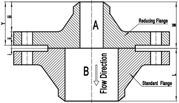
Figure-1: a reducing flange joint: reducing WN flange A and standard WN flange B.
As depicted in Figure-1, the reducing flange is generally constructed in 3 sections: i – flange facing, ii – flange thickness, iii – flange hub. Its characteristics are obvious: the facing dimensions, thickness, bolting dimensions, and outside diameter of the reducing flange are the same as those of the standard flange of the size from which the reduction is being made. The hub dimensions as well as the bore diameter of the reducing flange are generally the same as those of the standard flange of the size to which the reduction is being made.
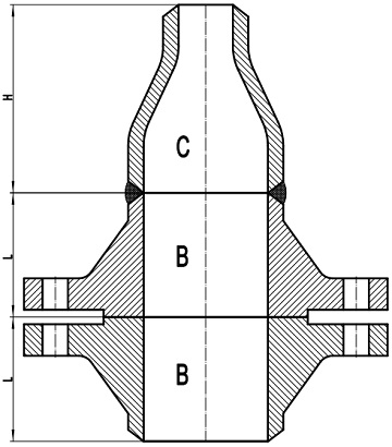
Figure-2: two standard welding neck flanges with one reducer to achieve the reduction in piping.
In order to make a reduction in the pipe line with two standard welding neck flanges, an additional reducer shall be used as illustrated in Figure-2. The overall length of this configuration is 2L+H, which is much longer than L+M of a reducing flanged joint as illustrated in Figure-1. It means that the use of reducing flanges can effectively save space in crowed situation. In fact, the reducing flange is most frequently used in installations with limited space.
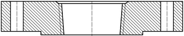
A typical reducing threaded flange without hub made from ASME B16.5 blind flanges.
Reducing flanges manufactured in accordance with ASME B16.5 are available in Class 150 through 2500. The facing of the reducing flange shall be the same as that of the mating standard flange. Generally, four types of reducing flanges are available according to the standard: reducing welding neck flanges, reducing slip on flanges, reducing threaded flanges, and reducing socket welding flanges. The reducing welding neck flange must be furnished with hub and the hub dimensions shall be the same as those of the standard flange of the size to which the reduction is being made. Reducing flanges of threaded, slip on or socket welding types may be furnished with or without hub. The hub dimensions shall be at least as large as those of standard flange of the size to which the reduction is being made. The hub may be larger or omitted as detailed in the table below.
| *Size A | *Size B |
|---|---|
| 1" | 1/2" |
| 1-1/4" | 1/2" |
| 1-1/2" | 1/2" |
| 2" | 1" |
| 2-1/2" | 1-1-4" |
| 3" | 1-1-4" |
| 3-1/2“ | 1-1/2" |
| 4" | 1-1/2" |
| 5" | 1-1/2" |
| 6" | 2-1/2" |
| 8" | 3" |
| 10" | 3-1/2" |
| 12" | 3-1/2" |
| 14" | 3-1/2" |
| 16" | 4" |
| 18" | 4" |
| 20" | 4" |
| 24" | 4" |
If the “smaller-end” (reducing outlet) of the flange is smaller than those listed in Column “Size B”, the reducing flange may be furnished without hub (made from a blind flange). Class 150 reducing threaded flanges do not have a counterbore. Class 300 and higher pressure reducing threaded flanges will have depth of counterbore Q of 7 mm for NPS 2 and smaller tapping and 9.50 mm for NPS 21∕2 and larger. The diameter Q of counterbore is the same as that given in the tables of threaded flanges for the corresponding tapping.
Reducing flanges shall be designated by the NPS for each opening. Two examples are provided below: